01
OFFICIAL DIGITAL OUTPUT DATA
Switching, protection & load limits
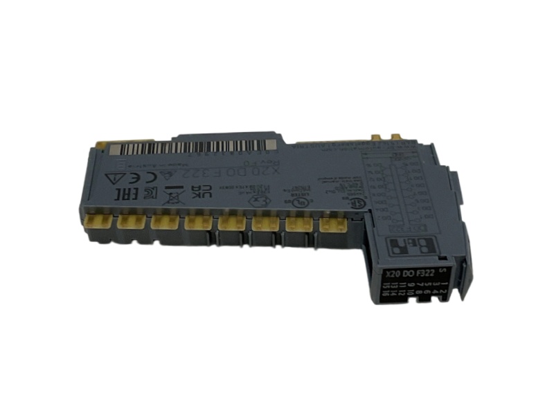
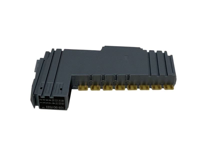
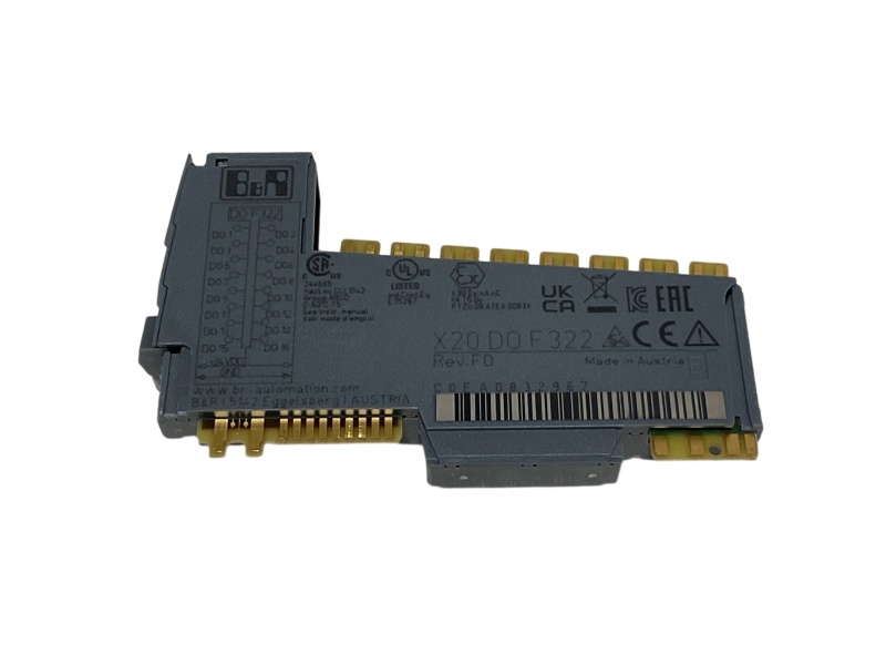
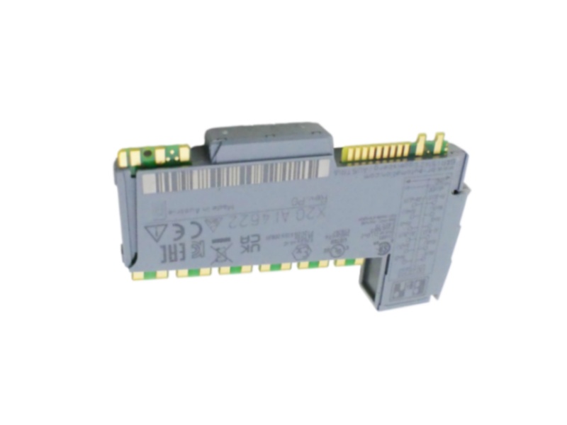
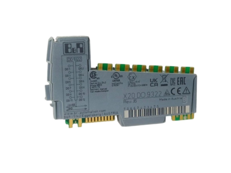
B&R output data arranged for timing, current capacity, short-circuit behavior, diagnostics, isolation and installation.
Output count16 digital channelsOutput circuitSource configuration
B&R ID code0xC0EAOvercurrent protectionThermal shutdown on overload or short circuit
Diagnostic indicatorsPer-channel I/O, operating state and module statusInductive-load handlingInternal freewheeling diode
Bus power consumption0.28 WDiagnostic responseOutput monitoring with 10 ms delay
Internal I/O power0.95 WOff-state leakage5 µA
Actuator-related dissipation+0.56 WRDS(on)140 mΩ
Turn-on delayBelow 300 µs on rising edgeShort-circuit peakBelow 3 A
Turn-off delayBelow 300 µs on falling edgeRestart after shutdownApproximately 10 ms, temperature-dependent
Resistive switching frequencyMaximum 500 HzInductive braking voltageTypically 45 VDC
Output technologyCurrent-sourcing FETChannel-to-bus insulation500 Veff
Nominal output voltage24 VDCElectrical isolationChannel isolated from bus only
Switching-voltage range24 VDC -15% / +20%Operating temperature-25 to 60°C horizontal; -25 to 50°C vertical
Nominal channel current0.5 ARelative humidity5 to 95%, non-condensing
Total nominal current8 ADegree of protectionIP20 per EN 60529
Connection method1-wire connectionsModule pitch12.5 +0.2 mm